0. Background
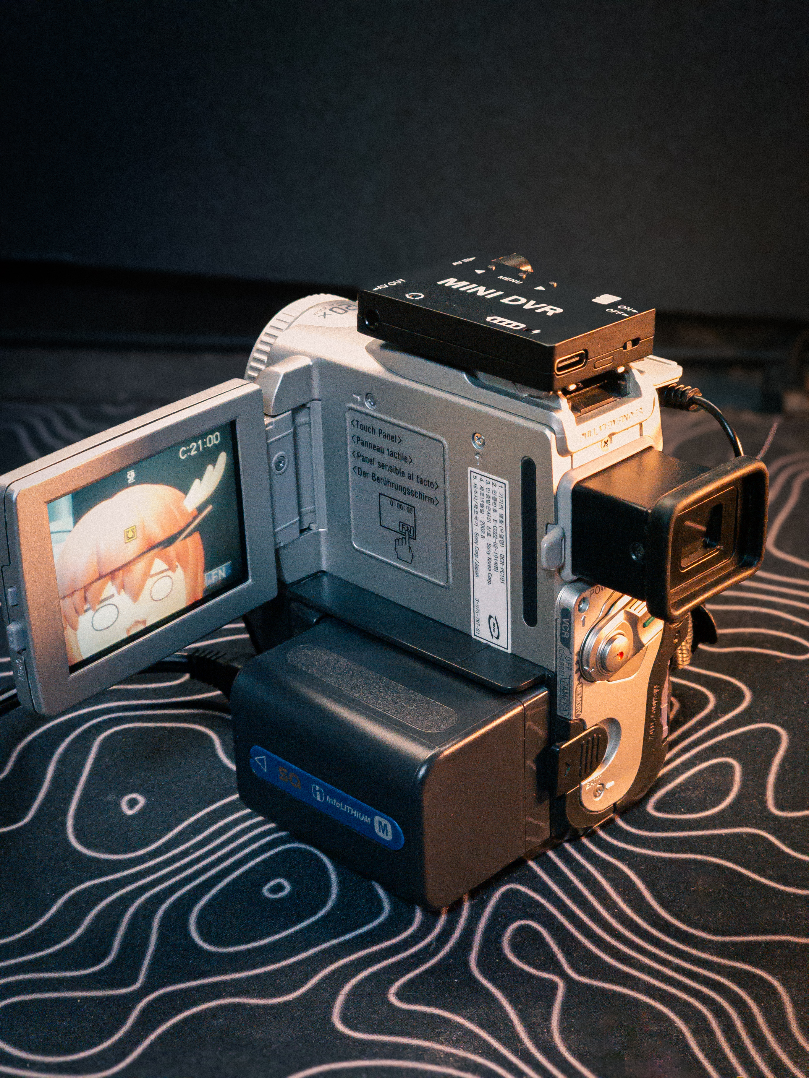
Riding the recent CCD-camera craze (partly fueled by NewJeans and others), I dug out my old Sony DCR-PC101 tape recorder to try shooting some footage with it. A few problems got in the way.
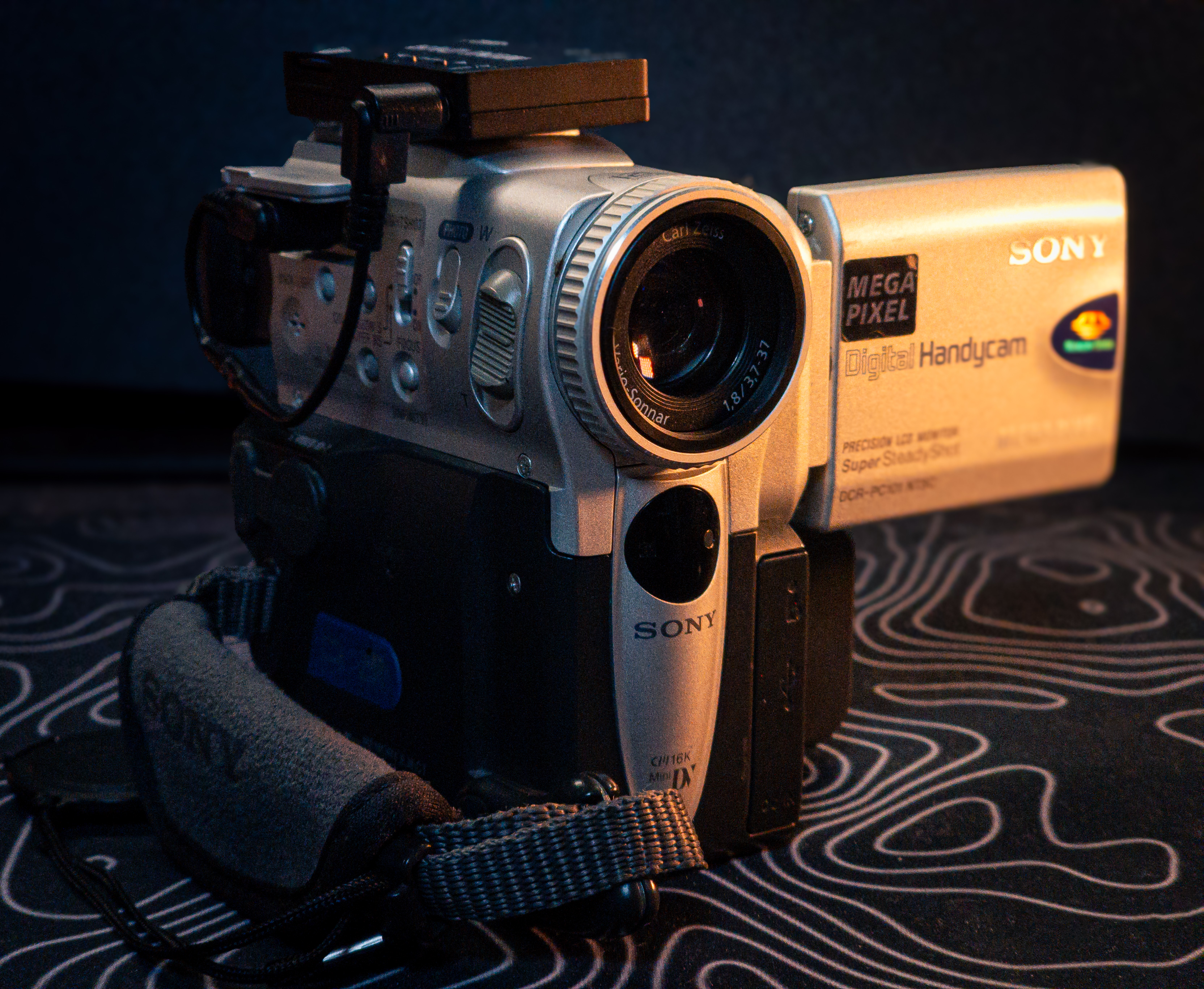
- MiniDV tape recording is hard to source tapes for, limited to 90 minutes per recording, and puts wear on physical parts.
- FireWire (IEEE-1394) capture is possible, but it means playing the tape back and manually recording the output — inefficient.
In other words, I needed to skip the tape-playback step entirely and piggyback a recording directly off the live video feed while shooting.
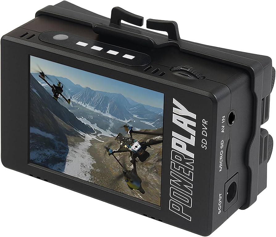
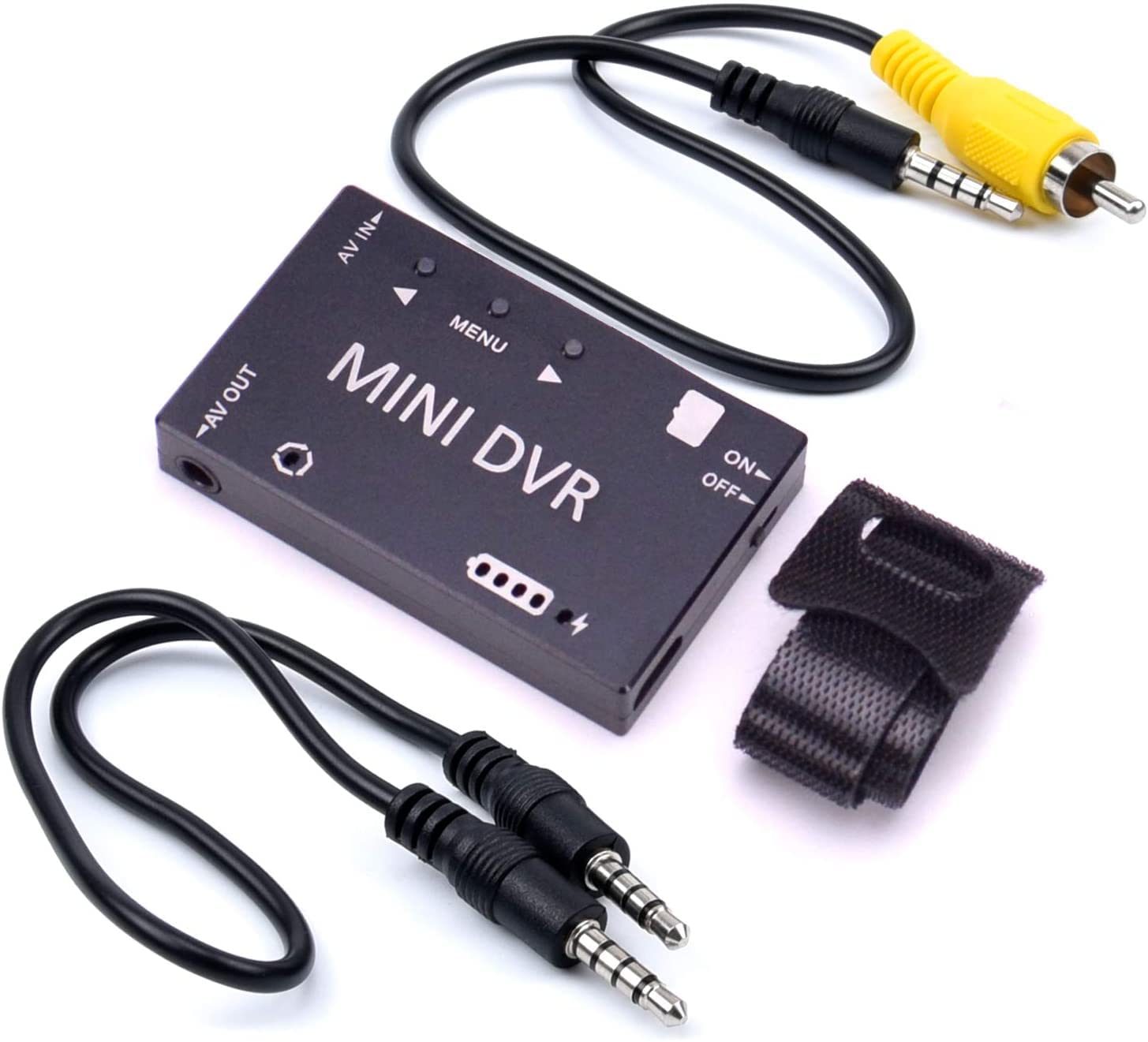
ImmersionRC’s PowerPlay DVR, recently popularized on social media, would let me record and monitor the feed at the same time, but its ~200USD price tag felt steep, so I looked for something closer to a DIY approach instead: the “Mini DVR” sold on AliExpress. It has no screen and only about two hours of battery life, but at under 20USD it makes for an extremely cost-effective quasi-digital-camera build.
 |
 |
1. Problem Definition
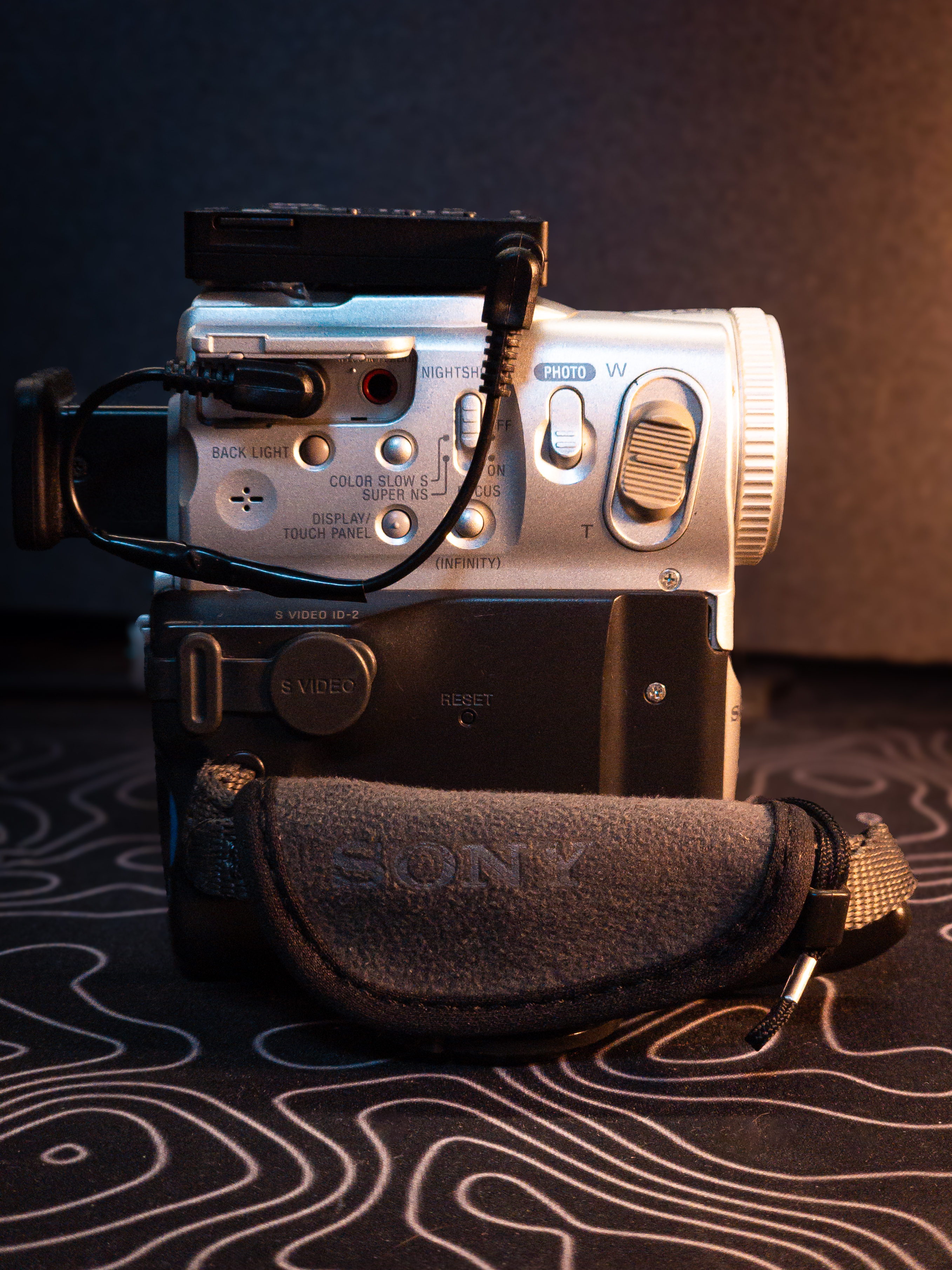
I assumed this would be a simple matter of piggybacking the video signal through a composite jack — but that’s exactly where the trouble starts. Sony, in their infinite wisdom, rewired its composite connector pinout however they pleased. So I had to cut the wires myself and rewire the connection by hand.
| Item | Detail |
|---|---|
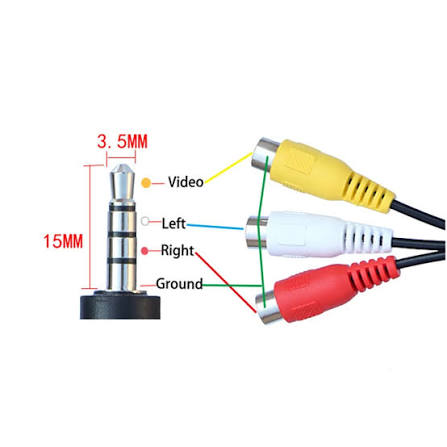
| PC101 A/V jack | 3.5mm TRRS - L, V, G, R |
| DVR AV-IN jack | 3.5mm TRRS - V, L, R, G |
 |
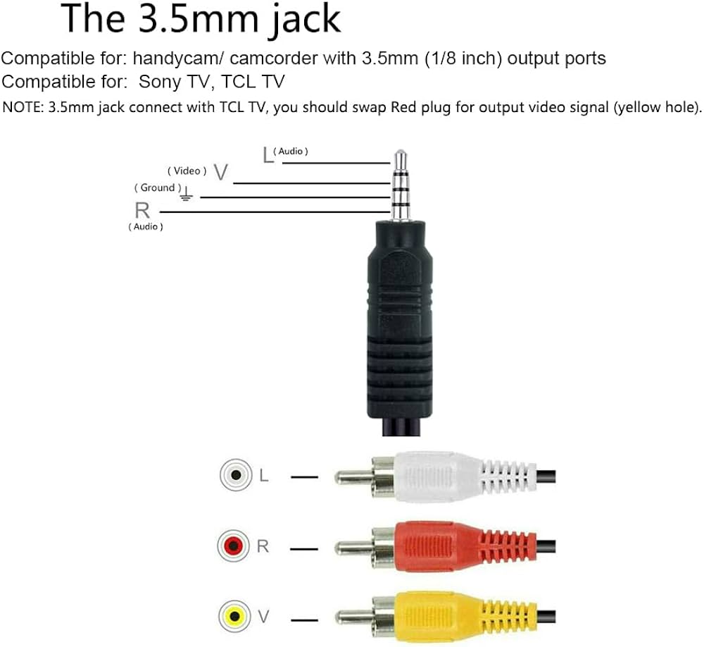 |
None of the pins line up, so plugging it straight in gives nothing but a black screen. The only way forward was to physically probe the pins to build a truth table, then cut the TRRS cable and rewire it.
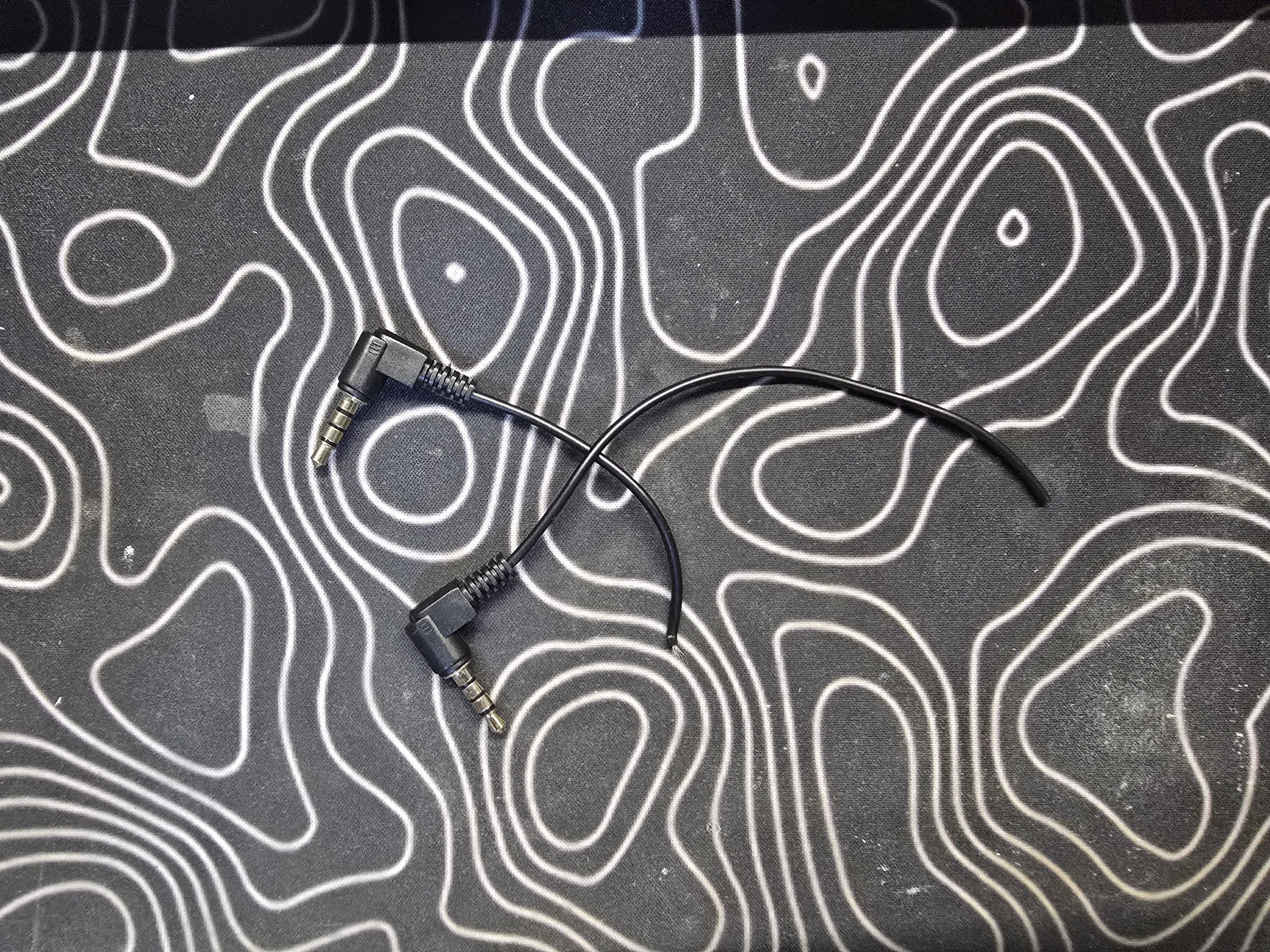
2. Method — Finding GND, Then Finding Video
- Multimeter continuity (resistance) mode → probe against the outer metal shell to find GND first
- Multimeter voltage (DCV/ACV) mode → find the 75Ω / video line (a composite signal swings wildly)
3. Troubleshooting Log
It took about three attempts to derive the correct truth table.
Attempt 1 — Guessing from resistance/voltage readings alone → Failed
| Measurement | Result | (Wrong) Interpretation |
|---|---|---|
| PC101 Blue | 1.5Ω, continuous to GND | Assumed “Blue = GND” |
| PC101 Green | Fluctuating 0.3–0.5V | Assumed “Green = Video” |
→ Soldered Green-to-Green, Blue-to-Blue. Result: no sound, black screen.
Why it was wrong: the PC101’s A/V jack is an output, so its Video pin doesn’t show low resistance to GND — resistance alone can’t identify Video. And the 0.3–0.5V reading on Green turned out to actually be an audio signal.
Attempt 2 — Estimating the pinout from the stock cable
Using Sony’s OEM cable, I traced the actual wiring truth values.
| Pin | Stock Cable Color | Signal |
|---|---|---|
| Tip | White | Audio L |
| Ring1 | Yellow | Video |
| Ring2 | — | GND |
| Sleeve | Red | Audio R |
Attempt 3 — Measuring each cut end separately
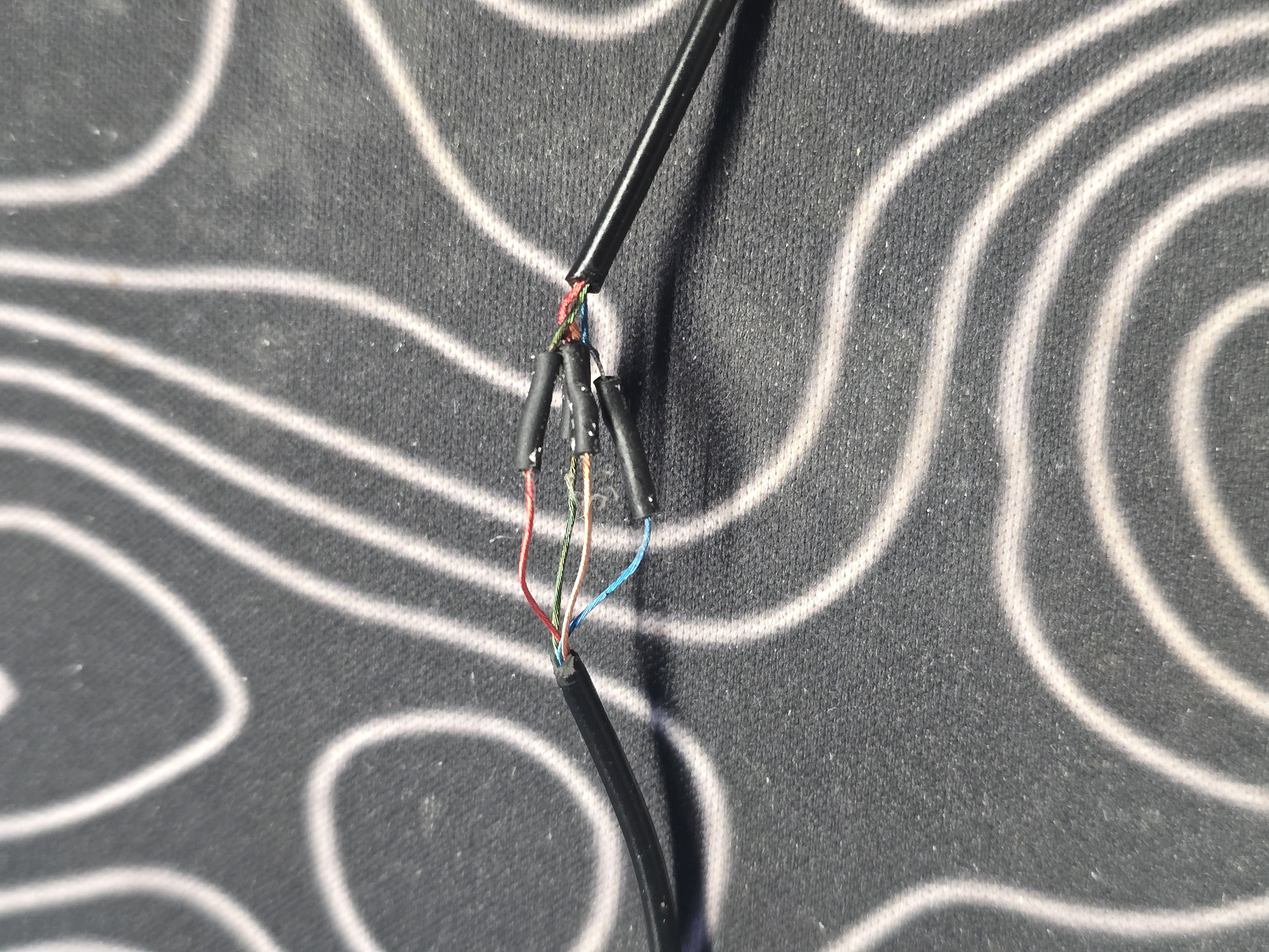
I located the same GND on both ends, then measured the DVR-side and PC101-side video lines separately to pin down the actual video wire on each side.
PC101-side cut end (voltage mode, Blue as COM):
- Orange → periodic swing between 0–0.3V = composite sync pulse = Video
- Blue = GND (4.1Ω)
DVR-side cut end (resistance mode):
- Green → exactly 75Ω = composite termination resistor = Video
- Blue = GND (1.5Ω)
4. Final Wiring Diagram
- Orange ↔ Green (Video)
- Blue ↔ Blue (Ground)
- Red → Orange (Audio L)
- Green → Red (Audio R)

4-4. Result
Image result:
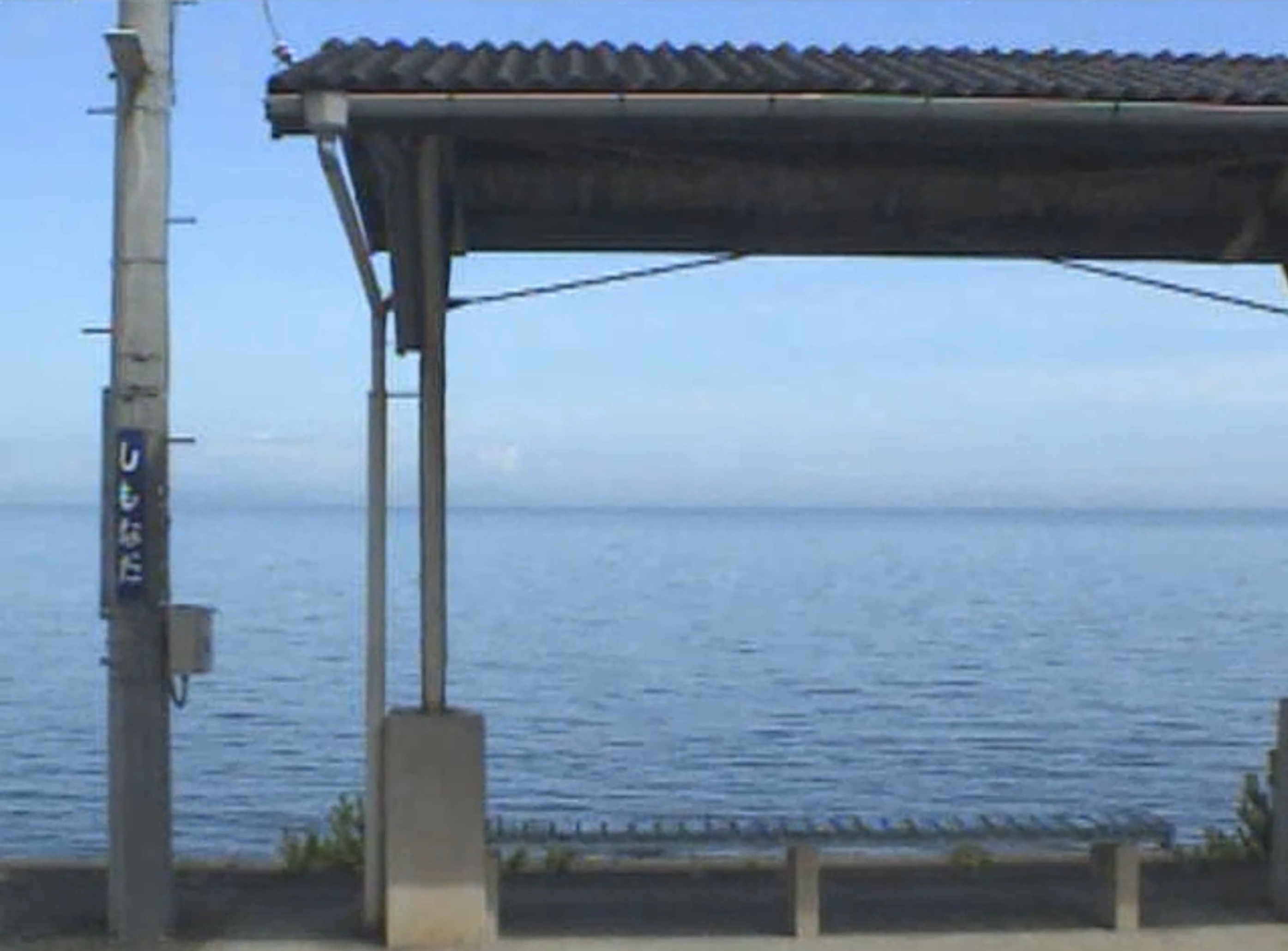
Video result: https://youtu.be/BxsPsBQSWJY
5. Conclusion
When probing signals, always look for a solid 75Ω on the DVR side and a 0–0.3V sync pulse on the camcorder side.
With that, the CCD 480i composite camera was fitted out for an ultra-cheap retro build. Everyone, embrace your inner retro aesthetic.
|
 |
 |