Overview
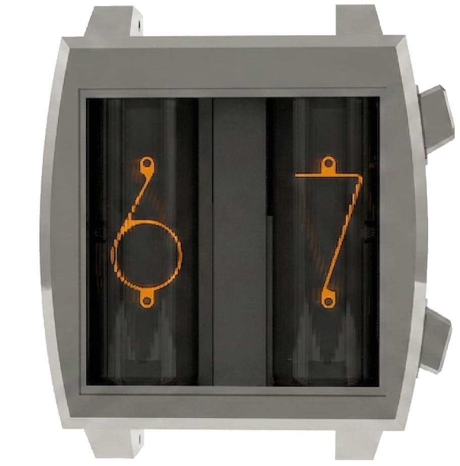
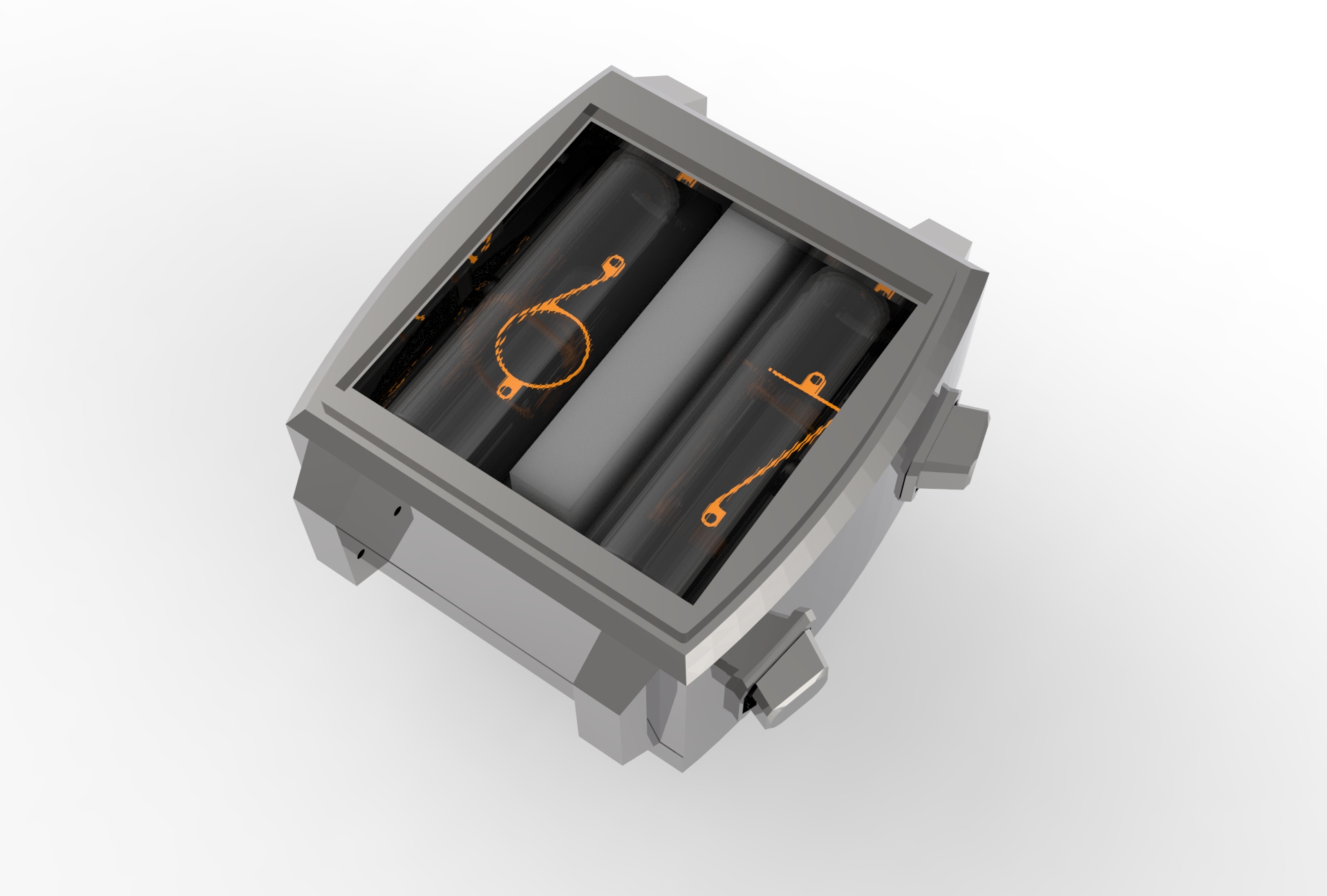
Soyuz (Союз) is a modular wristwatch project built around two NOS (New Old Stock) Nixie tubes. The goal was to turn the Nixie tube — one of the great feats of Cold War-era technology — into a brand of its own.

Key Specs (Targets)
| Item | Detail |
|---|---|
| Display | 2× Nixie tubes (IN-17, modular add-on) |
| MCU | ESP32-S3 (BLE 5 / Wi-Fi 2.4GHz) |
| Power | 1000mAh Li-Po, Qi 5W wireless charging |
| HV boost | 3.7V → 165V step-up, 3mA |
| Case | 6061 aluminum CNC (PLA+ for prototype), 35×35 square sapphire window |
| Interface | 8-pin board-to-board |
Problem Recognition
There’s no proper Nixie-tube wristwatch brand in Korea, and even overseas brands are hard to get without importing directly. Soyuz aims to be a wrist-worn platform built around a user-swappable Mezzanine module structure, where a single body can accept multiple kinds of display modules (Nixie / Numitron / VFD…).
Design
 |
 |
 |
Form Factor
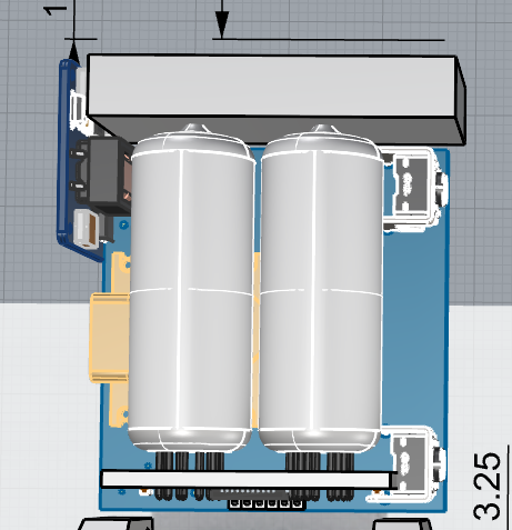
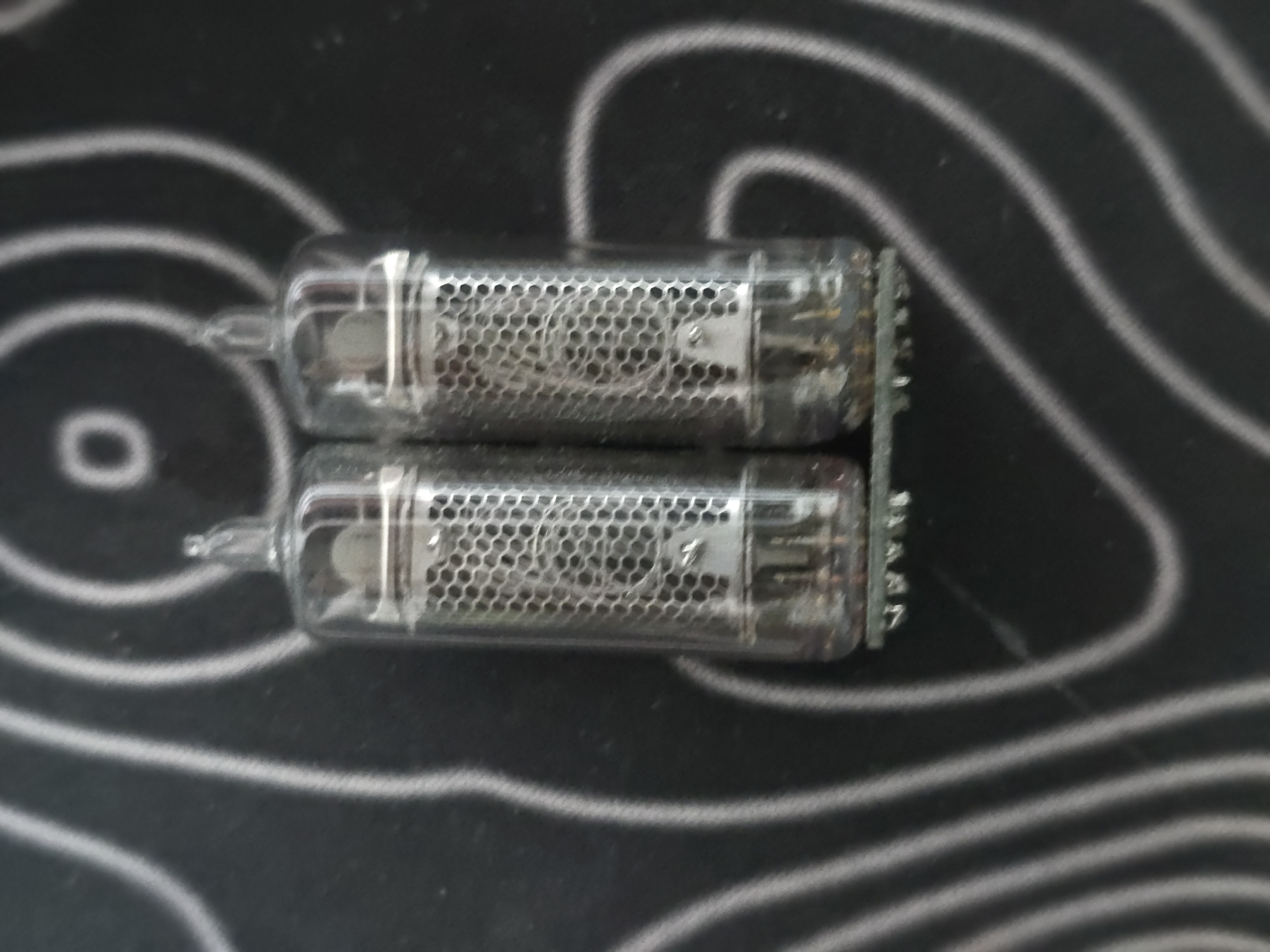
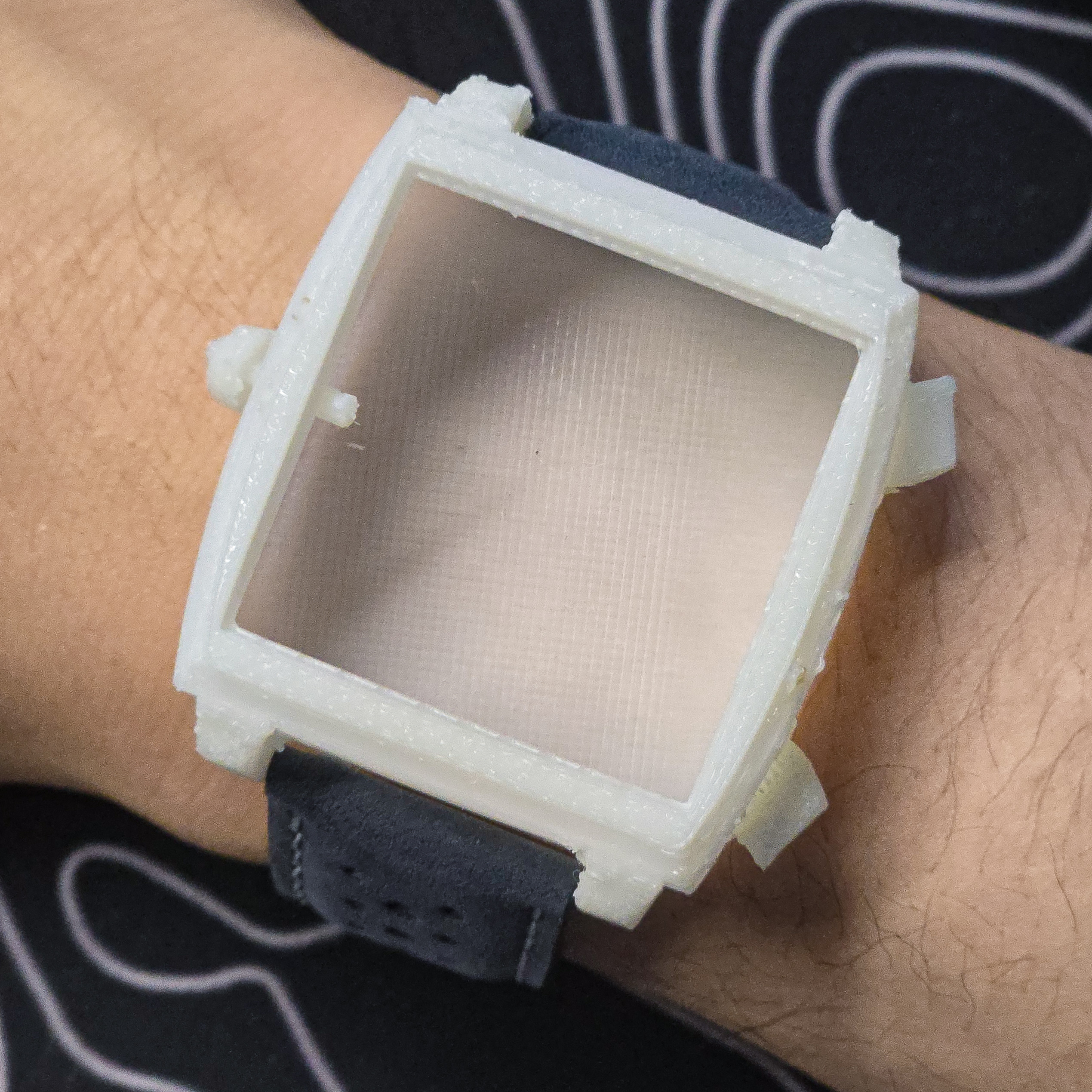
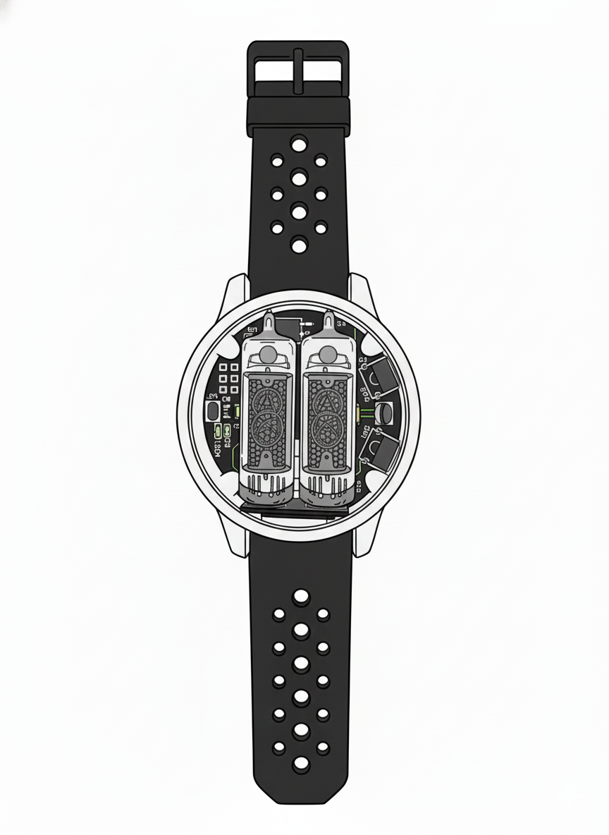
With a 35mm front sapphire, a Nixie tube roughly 14mm thick, plus the PCB and high-voltage circuitry, the case comes out to 40mm × 40mm × 18mm or larger — very much on the oversized end for a wristwatch. Even so, the goal was to make it feel like an object worn on the wrist, not just a watch.
 |
 |
 |
Case
- Current design: eSUN PLA+
- Planned prototype: 6061-T6 aluminum CNC, untreated hairline finish
- Production options: black/gray/titanium anodizing or SUS304 PVD
- Front window: 1–2T curved optical-grade sapphire, AR coated
- Strap: 24mm standard (racing strap)
Module Interface
The front Nixie module currently connects to the main body via a 2.54mm-pitch 8-pin connector, which carries all of the following over one connector:
- 170V HV (tube anode)
- 5V logic power
- SPI (shift-register data) — LE, DIN, CLK
- (future addition) an I2C line for module status reporting
This structure lets a user pull out a module and swap in a different type (Numitron, VFD) without tools, while the main body can read the driving profile of whichever module is installed.
Circuit Design
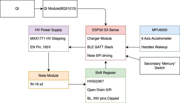
Overall Block Diagram
Display Driver
I chose the HV5523 (Microchip, a 32-channel high-voltage shift register rated up to 220V). Rather than a 1970s-style K155ID1/74141 BCD-to-decimal driver, a shift register was chosen for form factor and for driving more than 16 pins.
MCU
The prototype uses an ESP32-S3-SENSE module.
- BLE 5.0 + Wi-Fi 2.4GHz
- ~10μA in deep sleep
Charging / Power Management
- Qi 5W receiver: BQ51013B (TI)
- Li-ion charging uses the ESP32-S3’s built-in charge/discharge module
- System LDO: AP2112-3.3 (low-dropout, 600mA)
- Protection: built-in OVP/OCP plus an external PTC
Sensors
- IMU: MPU6050 6-axis accelerometer. Triggers an INT pin on jerk (wake-up) gesture detection
- Mercury switch: an extra switch added as secondary redundancy
PCB
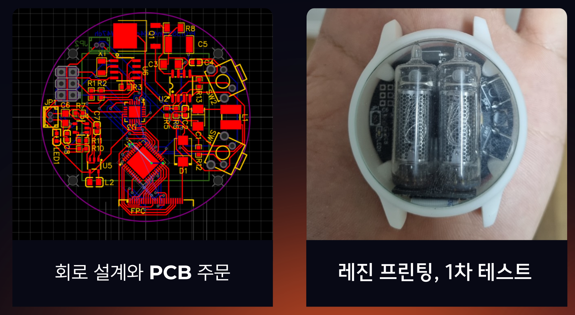
A 2-layer, 1.6mm FR-4 stack-up.
- L1 (Top): signals, components, 5V power
- L2: solid GND plane
- Main body PCB: 38 × 38mm
- Nixie module PCB: 30 × 18mm
Firmware Architecture
Built on ESP-IDF + FreeRTOS. The overall flow boils down to 5 tasks and 1 ISR.
Task Layout
| Task | Priority | Period | Role |
|---|---|---|---|
display_task |
10 | 5ms | HV5523 refresh, on-call, multiplexing, CORE1 |
power_task |
8 | 1s | battery/charging monitoring, low-power mode decisions, CORE0 |
sensor_task |
7 | IMU IRQ / mercury switch | wake-on-wrist, CORE0 |
ble_task |
6 | event-driven | GATT server, ANCS/AANS, OTA, CORE1 |
app_task |
5 | 100ms | mode switching, notification visualization, user settings, CORE0 |
Anti-Cathode-Poisoning
If a Nixie tube displays the same digit for too long, an insulating film forms on the unused cathode surfaces (spotting/poisoning), causing misfires. To prevent this, a daily “nuking” routine cycles through all digits (00–99). This runs as a routine executed once per day.
Time Sync
- When BLE-connected: synced to the phone’s clock at 1-second resolution
- Offline: ESP32’s built-in RTC (±20ppm) — roughly ±50 seconds of drift per month
OTA
Uses ESP-IDF’s esp_https_ota API. The partition table is a dual-slot layout — factory + ota_0 + ota_1 — with automatic rollback on boot failure. The Flutter phone app downloads the ROM file from a server and pushes it to the watch, which verifies the checksum before applying it.
Power Profile
| State | Average Current | Notes |
|---|---|---|
| Display ON (tube lit) | ~500mA | includes HV boost |
| Display OFF, BLE advertising | ~2mA | 1-second wake interval |
| Deep sleep | ~150μA | only RTC + IMU interrupts active |
At 100 wakes of 15 seconds per day, runtime is roughly 72 hours.
Assembly
Soyuz is built from 3 subassemblies.
1. Nixie Module (front, detachable)
- 2× Nixie tubes (socket-mounted, user-replaceable)
- HV5523 driver
- 8-pin, 2.54mm connector
2. Main Module (body)
- ESP32-S3-SENSE
- MAX1771 HV boost
- BQ51013B
- MPU6050
- 1000mAh Li-Po cell
Assembly Sequence
- SMT the Nixie module PCB → hand-solder the Nixie tube pins
- SMT the main PCB → flash firmware → test power/charging/BLE pairing
- Seat the main module + battery in the lower case → apply a silicone gasket
- Attach the front module → sapphire window + upper case → fasten with a torque driver
- Final functional test: time display, BLE connection, wireless charging, IMU wake-on-wrist, anti-poisoning routine
Roadmap (as of May 2026)
Trademark registration for “Soyuz” is currently complete.
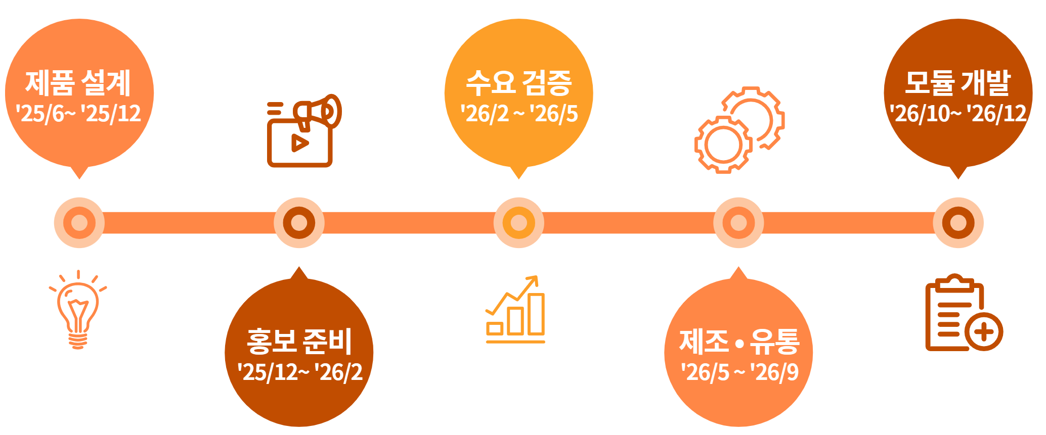
| Phase | Timeline | Key Deliverable |
|---|---|---|
| 1st prototype circuit build | Aug '26 – Oct '26 | validate custom HV boost / wireless charging circuit |
| MVP complete | Nov '26 | full assembly verified working |
| Module design IP secured | Nov '26 – Jan '27 | Mezzanine design filing |
| Crowdfunding prep | Dec '26 – Jan '27 | ads, influencers, campaign page |
| Crowdfunding | Jan '27 – Apr '27 | goal: 1,000 units |
| PCB mass production + KC certification | Apr '27 – Jun '27 | PCB SMT, certification complete |
| CNC case mass production | Apr '27 – Jun '27 | 1,000-unit run |
| First shipment | Jun '27 – Aug '27 | assembly, QC, shipping |
| Additional modules (Numitron/VFD) | Sep '27 – Nov '27 | next-generation module production |
Closing — What’s Next for the Modules
The plan is to keep any display module compatible as long as it matches the main body’s interface (18-pin, 170V/5V/SPI/I²C), and I’ll close this out with the two candidates under consideration for the next module.
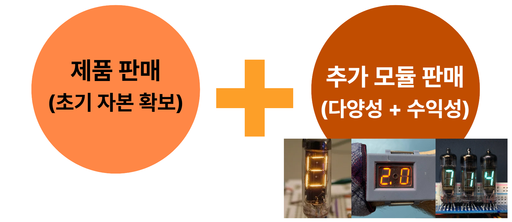
Numitron (IV-9, IV-16, RCA Numitron 3015)
The Numitron is a 7-segment incandescent display tube developed around the same era as the Nixie tube. A tungsten filament is shaped into 7 segments, giving it the same familiar letterform as the 7-segment digits on a typical digital clock.
Circuit-wise, it’s much simpler than a Nixie tube:
- No HV boost (170V) needed — drive directly at 4.5V or with a simple 5V boost
- The main body interface stays the same
Power draw is higher than a Nixie tube (the filament must stay heated continuously), but with the HV circuitry gone, overall system efficiency ends up about the same.
VFD (IV-18, IV-22)
A VFD (vacuum fluorescent display) glows cyan: electrons emitted from a heated cathode are accelerated toward a grid and strike a phosphor-coated anode, producing light. Since the voltage differs, a voltage-switching mechanism keyed to an EEPROM setting would need to be added.
Circuit-wise:
- Filament: 2.5V AC or PWM driven
- Grid/segments: roughly 30V (HV5523) — just needs the MAX1771’s output voltage lowered
- Supports multiple digits (8-digit, 16-digit) → extended usability like alarm time, date, or short message display
Coming Up
Circuit design, firmware development logs, and the production process will keep being shared as a series on this blog.